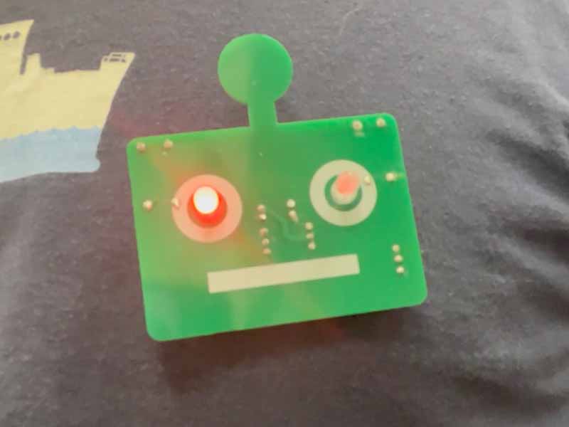
Blinking robot badge

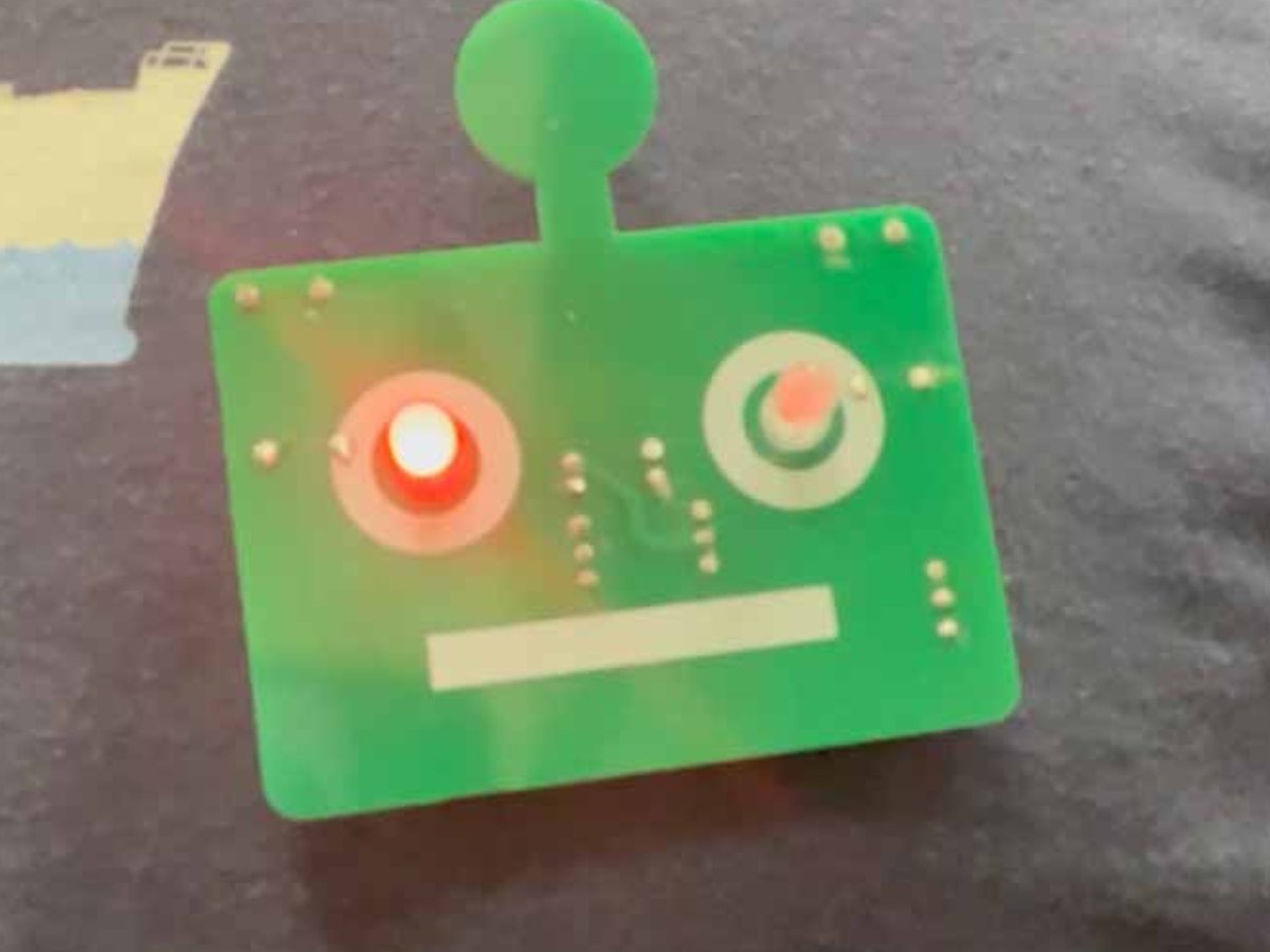
Create your very own blinking robot badge! You will be making a 'flip-flop' cirquit to make the lights blink one after the other.

Age
9+ yrs
Time
45–60 min
PDF

What do you need?

Materials

  • Robot circuit board
  • 2x LED's
  • 2x xxxOhm resistors
  • 2x xxxOhm resistors
  • 2x BC547 transistors
  • 2x ...uF capacitors
  • Toggle switch
  • Coin cell battery holder
  • Badge pin
  • CR2032 battery

Tools

  • Soldering iron
  • Flush cutter
  • Glue gun
  • Tweezers

Steps

1

Resistors

  • Good to knowWhen soldering PCB boards it's good practice to start with the lowest components. If you do taller components first they might get in the way later on.
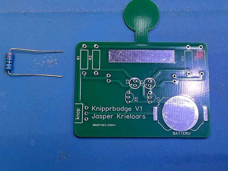
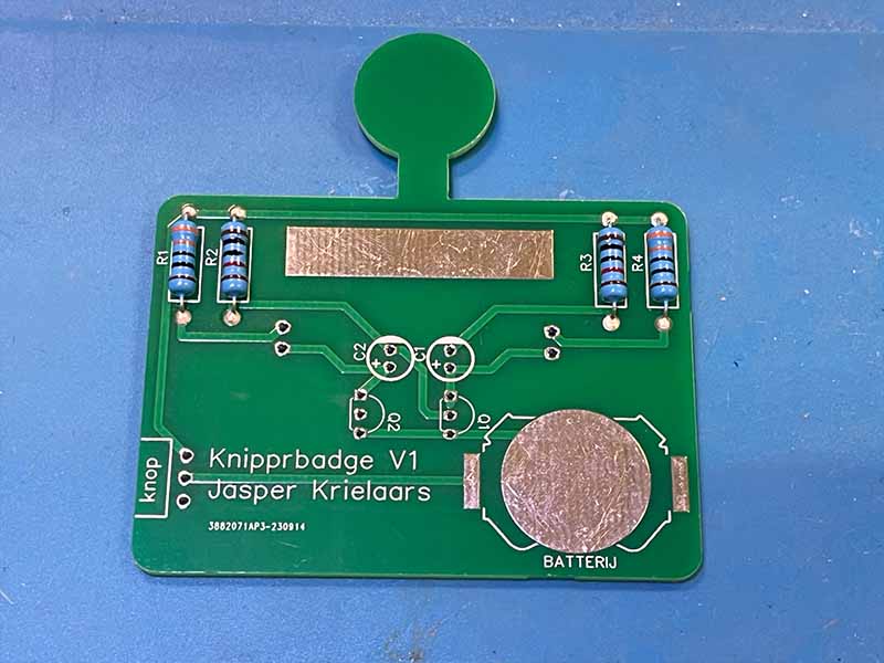
  • Place the resistors in the holes. The ones with the red band go in R1 and R3, the ones with the orange band go in R2 and R4.
  • Bend the legs from the other side so they don't fall out
  • Solder the resistors to the PCB board
  • Use the flush cutter to trim the resistor legs down to the board
2

Transistors

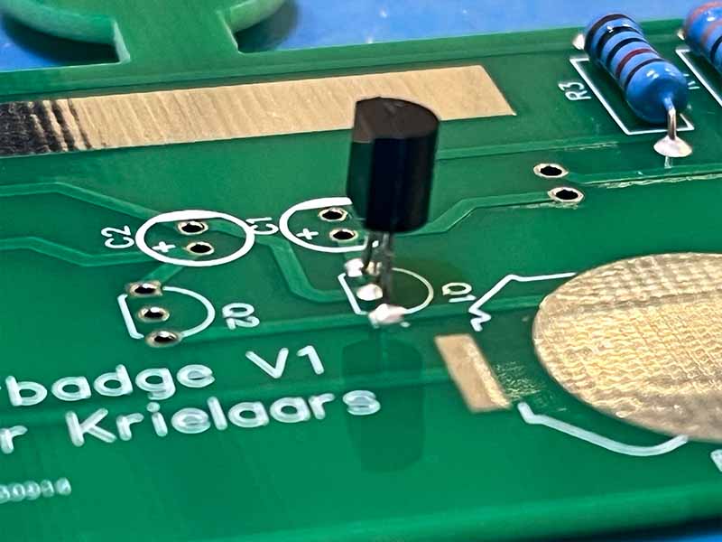
  • Watch outTransistors are polarised. This means that when you place them the wrong way round your circuit won't work.
  • Place the 2 transistors in the holes marked Q1 and Q2. Make sure to match the shape of the component to the printed shape on the circuit board.
  • Bend the legs and solder and trim like you did with the resistors.
3

Capacitors

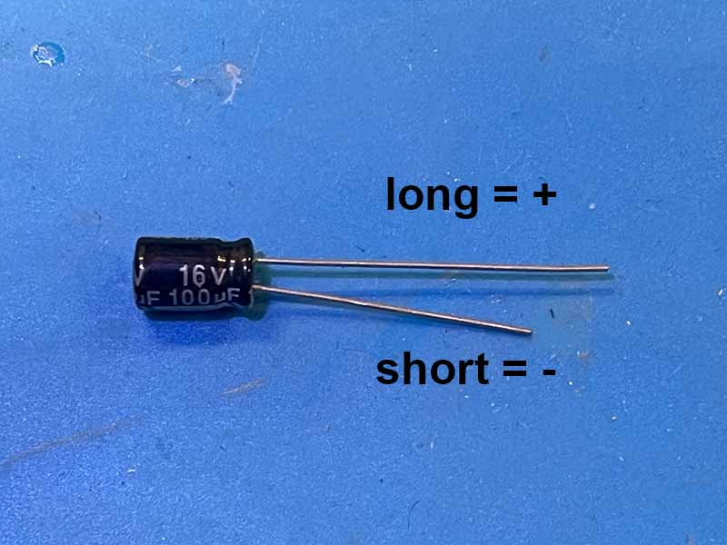
  • Watch outCapacitors are polarised. This means that when you place them the wrong way round your circuit won't work.
  • Place the 2 capacitors in the holes marked C1 and C2. Make sure that the long leg goes in the hole marked with the +.
  • Bend the legs and solder and trim like you did with the resistors.
4

Switch

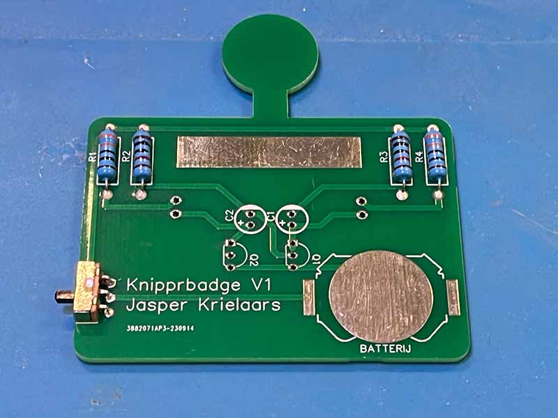
  • Place the switch in the holes marked 'knop'. The switch should point outwards.
  • Solder and trim like you did with the resistors.
5

Battery holder

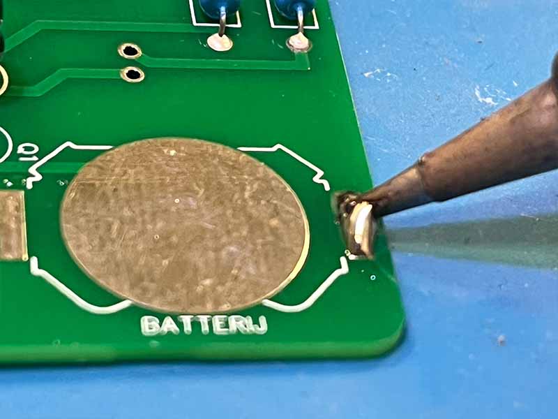
  • Watch outMake sure to mount the battery holder in such a way that the biggest opening is at the bottom of the board. Otherwise there is not enough room to slide the battery in.
  • Melt some soldering tin to one of the battery pads.
  • Place the battery holder on the pad and hold it down with a pair of tweezers.
  • Attach the battery holder by re-heating the pad with the solder already on it.
  • Solder the other side of the battery holder down to the pad.
6

LED's

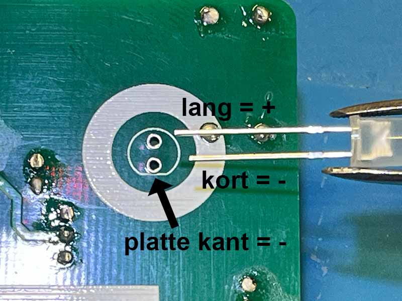
  • Watch outLED's are polarised. This means that when you place them the wrong way round your circuit won't work.
  • From the other side of the board, place the LED's onto the board. Make sure the longer leg go trough the holes marked with the +
  • Bend, solder and trim.
7

The Pin

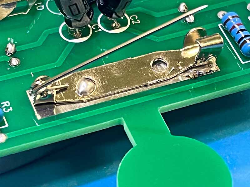
  • Good to knowWhen soldering bigger components, it will take longer for the soldering iron longer to heat up the component.
  • Like with the battery holder, place some tin on the pad, than melt it again while holding the pin down with a pair of tweezers
8

Re-inforce

  • Good to knowThe button is only attached trough 3 small metal legs. They can easily bend or break.
  • Use the glue gun to glue the button to the board, thereby making it less likely to break when switching.
9

Battery and... DONE!

  • Place the battery with the + side away from the circuit board.
  • DONE!